What Is a 25G SFP28 Transceiver and How Does It Work?

Time:2026-10-15 Author:Mason
0%

A 25G SFP28 transceiver is a compact, pluggable device that connects network equipment through fiber or copper cabling. It supports 25 Gigabit Ethernet links while using the familiar SFP28 form factor. This makes it useful in modern data centers, server connections, and switch uplinks where 10GbE no longer provides enough capacity.

The transceiver converts electrical signals from a switch or network card into optical signals. A laser sends those signals through fiber. At the receiving end, a photodiode converts them back into electrical data. With compatible equipment, the link can transmit at approximately 25.78125 Gbps, supporting efficient data movement with low latency. Different versions serve different distances, from short multimode fiber links inside a rack to longer single-mode connections between network rooms.

It is easy to describe this module as a simple speed upgrade. That explanation is incomplete. Compatibility depends on wavelength, fiber type, connector, coding, power limits, and switch support. A 25G SFP28 transceiver may also support direct-attach copper for short server connections, but copper and optical models are not interchangeable. Practical installation requires checking the equipment manual, port configuration, and optical budget. Small details matter.

This guide explains the transceiver’s internal operation, common module types, network applications, compatibility requirements, and installation considerations. It also examines limitations that product descriptions sometimes overlook. Real-world performance depends on the complete link, not the module alone.
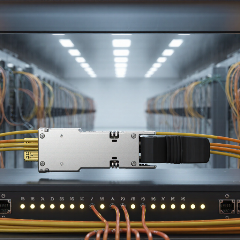
What Is a 25G SFP28 Transceiver and How Does It Work?

25G SFP28 Definition: A 25.78 Gb/s Single-Lane Optical Transceiver

A 25G SFP28 transceiver is a compact, single-lane optical module for 25 Gigabit Ethernet links. Its standard line rate is 25.78 Gb/s, often written as 25.78125 Gb/s. IEEE 802.3by defines the 25GbE electrical and Ethernet requirements, while SFF-8431 and SFF-8472 describe related module interfaces and monitoring functions. SFP28 is the form factor, not the optical distance.

The module converts electrical data into light through an optical transmitter. A receiver changes incoming light back into electrical signals. Most 25G designs use NRZ signaling over one lane, reducing cabling complexity compared with multi-lane systems. Short-reach versions commonly support 70 meters on OM3 fiber or 100 meters on OM4 fiber. Single-mode variants can reach 10 kilometers, depending on the optical budget and specification.

The 25.78 Gb/s figure matters. It includes line coding overhead, so usable Ethernet throughput is slightly lower than the raw rate. The Ethernet Alliance 2023 Ethernet Roadmap identifies 25GbE as an established data-center speed for server-to-switch connections. Industry forecasts from LightCounting also continue to track strong demand for higher-speed optical modules as data-center traffic expands. These reports describe market direction, not guaranteed deployment results. Real performance still depends on fiber quality, connector cleanliness, temperature, and switch compatibility. The label alone is not enough.

SFP28 Architecture: How TOSA, ROSA, CDR, and the Host Interface Connect

A 25G SFP28 transceiver converts electrical data into optical signals and back again. Its compact housing contains several coordinated blocks. The host interface carries differential electrical signals between the switch and module. It also supports management communication, usually through a low-speed control bus. Power enters through dedicated pins, while the module monitors temperature, voltage, and optical status.

On the transmit side, the host sends a high-speed data stream to the CDR. The clock and data recovery circuit restores timing and reduces accumulated jitter. A laser driver then shapes the signal for the TOSA, which contains the laser and optical coupling components. The TOSA launches light into a fiber. At nominal 25GbE operation, the signaling rate is close to 25.78125 GBd. Small timing errors still matter.

The receive path works in reverse. Light reaches the ROSA, where a photodiode converts it into a weak electrical current. A transimpedance amplifier increases that current into a usable voltage signal. The receive CDR cleans the timing before sending data through the host interface. In practical testing, poor fiber alignment or excessive connector loss can resemble a faulty CDR. That distinction is easy to miss. Thermal conditions also affect laser power and receiver sensitivity. The architecture is often shown as a straight chain, but real modules include feedback loops, protection circuits, and monitoring logic. This simplified view remains useful, though it should not replace a datasheet-level check.

Transmission Process: From 25.78125 GBd Electrical Signals to Optical Data

A 25G SFP28 transceiver converts high-speed electrical data into optical signals for short- or medium-distance network links. Its host interface receives a differential signal at 25.78125 GBd. In common 25GbE systems, this signal uses NRZ modulation, carrying one bit per symbol. The actual data stream includes line coding and overhead, so the electrical rate is slightly higher than the useful payload rate.

The conversion begins inside the transmitter. Input equalization compensates for loss in the host circuit board and connector. A clock recovery circuit helps align the data transitions. Then, a laser driver changes the cleaned electrical waveform into controlled current pulses. The laser emits matching optical intensity changes through the fiber. Fast work happens here.

At the receiving end, a photodiode detects tiny changes in light. A transimpedance amplifier converts those changes into voltage. Limiting amplification and clock recovery rebuild a usable electrical output for the switch or server. Monitoring circuits may track temperature, voltage, and optical power during operation.

The process is not perfectly clean. Fiber loss, connector contamination, electrical noise, and temperature can close the eye diagram. Engineers therefore check insertion loss, receiver sensitivity, and bit error performance under realistic conditions. A simple block diagram hides these compromises. In practice, stable transmission depends on every stage, not only the laser.

Reach and Fiber Options: 850 nm over 100 m OM4 or 1310 nm over 10 km

What Is a 25G SFP28 Transceiver and How Does It Work?

A 25G SFP28 transceiver carries Ethernet traffic at 25 gigabits per second. It converts electrical signals into optical pulses, then converts received light back into data. The module usually connects through a duplex LC fiber interface. IEEE 802.3by defines the 25GbE electrical and optical framework, including short-reach and longer-reach applications. That standard matters because compatibility is more than matching speed.

The 850 nm option uses multimode OM4 fiber and can reach 100 meters. This distance suits server rooms, leaf-and-spine links, and short data-center rows. OM4 has a 50/125-micrometer core and supports high bandwidth with relatively low-cost optics. The Ethernet Alliance’s Ethernet Roadmap identifies 25GbE as an important step between 10GbE and higher-speed data-center networks. Still, 100 meters is a design limit, not a guarantee. Patch panels, dirty connectors, and tight bends reduce the practical margin.

For longer paths, 1310 nm single-mode optics can reach 10 kilometers. IEEE 802.3 specifications commonly associate this reach with 25GBASE-LR-class links. Single-mode fiber has a much smaller core, so alignment becomes less forgiving during installation. The advantage is clear: lower attenuation and longer campus or metropolitan connections. Field measurements should include insertion loss, polarity, and optical power. A link may appear healthy while operating close to its receiver threshold. That deserves a second look.

What Is a 25G SFP28 Transceiver and How Does It Work?

A 25G SFP28 transceiver converts electrical data into optical signals and back again. Reach depends mainly on wavelength and fiber type: 850 nm multimode fiber supports up to 100 m over OM4, while 1310 nm single-mode fiber supports up to 10 km.

Key takeaway: 850 nm over OM4 is suitable for short data-center links, while 1310 nm over single-mode fiber is designed for much longer connections.

Deployment Standards: 25GbE Compliance, SFP28 MSA, and Host Compatibility

A 25G SFP28 transceiver connects a host system to a 25GbE network. It converts electrical signals into optical or copper signals. On fiber, the module sends data through one high-speed channel. On copper, it supports short, direct connections inside a rack. Small module. Serious timing.

Deployment must match the 25GbE standard used by the network. Common options include 25GBASE-SR for short multimode fiber and 25GBASE-LR for longer single-mode links. The SFP28 MSA defines the module’s size, connector position, and electrical interface. However, MSA compliance does not guarantee full host compatibility. The switch port must support 25GbE operation, not merely accept an SFP28-shaped module. Firmware, link training, and FEC settings can also affect stability.

A practical installation begins with the host specification. Check supported speed modes, FEC requirements, cable type, and maximum reach. Then verify fiber polarity and connector cleanliness. A link may show light but still produce errors. That detail is often missed.

Digital diagnostics can reveal temperature, voltage, and optical power during testing. In a real rack, heat and airflow matter too. Two modules may meet the same standard yet behave differently under poor cooling. I would not treat the standard sheet as the whole answer. Test the exact module, host port, and cable together before wider deployment.

FAQS

What is a 25G SFP28 transceiver?

It is a compact optical module for 25-gigabit Ethernet links. It uses one data lane. The form factor does not define distance.

How does a 25G SFP28 module work?

A transmitter changes electrical data into light. A receiver changes incoming light back into electrical signals. Duplex fiber usually carries both directions.

What does 25.78 Gb/s mean?

It is the module’s raw line rate. Coding overhead slightly reduces usable Ethernet throughput. The label is not the complete performance story.

How far can a short-reach version transmit?

A multimode version commonly reaches 70 meters over OM3 fiber. With OM4 fiber, the typical limit is 100 meters. Actual margin may be smaller.

When is single-mode fiber more suitable?

Single-mode optics can reach about 10 kilometers with suitable specifications. They fit longer campus or metropolitan links. Installation alignment needs greater care.

What wavelengths are commonly used?

Short-reach optics commonly use 850 nanometers. Longer-reach optics commonly use 1310 nanometers. Wavelength alone does not guarantee compatibility.

What can reduce the real transmission distance?

Dirty connectors, tight bends, poor fiber, and patch-panel losses reduce link margin. Temperature can also affect performance. Small details matter here.

How should a 25G link be checked?

Verify fiber type, connector polarity, insertion loss, and optical power. Check switch compatibility too. A working link may still be near its receiver threshold. That deserves another measurement.

Conclusion

A 25G SFP28 transceiver is a compact, single-lane optical module designed to transmit and receive data at approximately 25.78 Gb/s. It typically combines a transmitter optical subassembly (TOSA), receiver optical subassembly (ROSA), clock and data recovery (CDR) circuitry, and a host electrical interface within the SFP28 form factor. The host system supplies high-speed electrical signals, while the module converts them into optical signals for transmission and changes incoming light back into electrical data.

During operation, the module processes electrical data at a signaling rate of 25.78125 GBd, encodes it as optical information, and sends it through a suitable fiber connection. Depending on the optical design, a 25G SFP28 transceiver may support 850 nm multimode transmission over up to 100 meters of OM4 fiber or 1310 nm single-mode transmission over distances reaching 10 kilometers. Successful deployment requires compatibility with 25GbE requirements, the SFP28 MSA, host port specifications, and the selected fiber type.

Mason

Mason

Mason is a seasoned marketing professional with a deep expertise in the company's offerings and a passion for driving brand awareness. With a strong background in digital marketing strategies, he has an innate ability to connect with diverse audiences and effectively communicate product benefits.......