Choosing a single mode transceiver is no longer a simple plug-and-play decision. Cloud workloads, 5G backhaul, and data-center traffic keep pushing optical networks toward higher capacity and longer reach. Cisco’s Annual Internet Report projected 5.3 billion internet users and 29.3 billion connected devices by 2023. That scale explains why link stability matters as much as headline speed.
Industry research adds useful context. LightCounting’s 2024 optical market analysis highlights artificial intelligence clusters and data-center upgrades as major demand drivers. The report also shows how quickly interface requirements are changing. Meanwhile, IEEE 802.3 standards and the SFF-8472 specification provide essential guidance for Ethernet performance, diagnostics, and management. These documents are not just technical paperwork. They help engineers verify wavelength, reach, power limits, and interoperability before installation.
The practical choice still depends on the real link. A 10Gbps module for a 2-kilometer campus connection may be unsuitable for a dense 400Gbps data-center fabric. Fiber type, connector cleanliness, insertion loss, temperature, and switch compatibility can change the outcome. Small details matter.
That part is often missed.
The seven tips in this guide focus on those details, including standards compliance, transmission distance, wavelength, module form factor, vendor testing, and total operating cost. A lower purchase price can become expensive after optics fail, cooling rises, or troubleshooting consumes engineering hours. No checklist is perfect, either. Some network environments have undocumented legacy constraints. Careful measurements and vendor validation remain necessary when selecting a single mode transceiver.
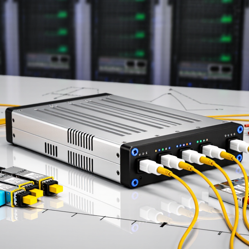
Choosing a single-mode transceiver starts with defining the network, not selecting a part number. Map the link distance, fiber route, data rate, wavelength, connector type, and operating temperature. A 10-kilometer path needs different optical performance from a 40-kilometer path. Include patch panels and splices in the loss budget. Small details matter.
The International Telecommunication Union reported 5.4 billion people online in 2023, increasing pressure on reliable network capacity. TeleGeography’s 2024 Global Bandwidth Research Service reported that international bandwidth demand grew by about 29% between 2022 and 2023. These figures support careful capacity planning, especially for data centers and long-haul links. Choose a transceiver that supports the required speed today, while allowing reasonable growth. Over-specifying reach can increase cost without improving the network.
Check transmitter power, receiver sensitivity, dispersion limits, and allowable attenuation. Confirm that the module matches the fiber type and required wavelength. Single-mode links may appear simple, but mismatched optics can cause unstable performance. I have seen clean installation drawings hide excessive connector loss. That is an easy mistake. Review standards compliance, digital diagnostics, interoperability, and temperature ratings before deployment. Vendor test reports help, but independent field measurements are more convincing. A power meter and optical time-domain reflectometer can reveal problems that software alarms miss. Plan for maintenance access, spare units, and future upgrades. The perfect specification rarely survives the first site visit.
A single mode transceiver should match both the installed fiber and the required transmission distance. Check the cable label before ordering. OS2 fiber usually supports longer links than OS1, but the transceiver must still use a compatible wavelength and connector type. A 1310 nm module may suit a medium-distance link, while longer routes often require different optical specifications. The numbers matter.
Measure the actual link, not just the distance between buildings. Add patch panels, connectors, and planned repairs to the calculation. Each connection introduces insertion loss. Then compare the total loss with the transceiver’s power budget.
A module rated for 40 kilometers may perform poorly on a damaged 12-kilometer cable. Too much optical power can also overload a short receiver. That detail is easy to miss.
Temperature and network speed also deserve attention. Industrial cabinets may become hot, so verify the operating range in the equipment datasheet. Confirm that the transceiver supports the switch port’s speed, duplex mode, and monitoring functions. In field checks, technicians sometimes trust a familiar specification and skip fiber inspection. That shortcut can create intermittent errors. I have found that cleaning connectors and testing with an optical power meter often reveals the real problem. Distance is only one part of the match. Cost-driven choices can look reasonable, but a small mismatch may lead to repeated replacements and unclear fault reports.
7 Tips for Choosing a Single Mode Transceiver?
Compare Wavelength, Data Rate, and Connector Specifications
When choosing a single-mode transceiver, start with wavelength compatibility. Check the fiber’s operating window, not just the module label. A 1310 nm optic may suit short metropolitan links, while 1550 nm often supports longer reaches. Confirm the required transmission distance and leave practical power margin. Tiny losses add up.
Match the transceiver’s data rate to the switch, router, and network standard. A higher rate does not automatically improve an older system. Verify the port type, duplex operation, and required fiber count. Some links use two fibers, while others send and receive over one fiber. I have seen installations fail because engineers checked speed but ignored optical budget. That mistake is expensive. Also review temperature ratings for outdoor cabinets and crowded racks.
Connector details deserve equal attention. Confirm whether the equipment requires LC, SC, or another approved interface. Polish type matters too; incompatible ends can increase reflection and insertion loss. Inspect every connector with a cleaning tool and microscope before connection. Dust is small. Its impact is not. Keep the connector boot aligned, avoid sharp bends, and confirm the keying direction. Read the datasheet carefully, including maximum reach, transmit power, receiver sensitivity, and diagnostic features. I still recheck these values before deployment because specifications can be misunderstood, especially when “maximum distance” assumes ideal cable conditions.
| Tip | Specification to Compare | Typical Options | Representative Single Mode Configuration | Selection Guidance |
|---|---|---|---|---|
| 1. Match the data rate | Transmission speed and interface standard | 1 Gb/s, 10 Gb/s, 25 Gb/s, 40 Gb/s, 100 Gb/s |
10 Gb/s SFP+ Commonly used with 10G Ethernet interfaces |
Select a transceiver whose data rate is supported by both the optical module and the host device. A higher-rate module is not automatically compatible with a lower-rate port. |
| 2. Verify the wavelength | Optical center wavelength and wavelength architecture | 850 nm, 1310 nm, 1550 nm; CWDM or DWDM channel wavelengths |
1310 nm Widely used for standard single mode Ethernet links |
Use 1310 nm for many short- and medium-distance single mode links. Use 1550 nm or DWDM wavelengths when longer reach, optical amplification, or wavelength multiplexing is required. |
| 3. Check the transmission distance | Specified reach over single mode fiber | 2 km, 10 km, 20 km, 40 km, 80 km or more |
10GBASE-LR: up to 10 km Typically specified over duplex single mode fiber |
Choose a reach rating that exceeds the calculated fiber path, including patch panels and expected losses. Actual distance depends on link budget, splices, connectors, and fiber quality. |
| 4. Compare the connector type | Optical connector and fiber polarity | Duplex LC, duplex SC, MPO/MTP, simplex LC |
Duplex LC Common for 1G, 10G, and 25G single mode duplex links |
Confirm that the connector matches the installed patch panel and cable. Parallel-fiber modules, such as some 40G and 100G designs, may use MPO/MTP connectors instead of duplex LC. |
| 5. Confirm the fiber configuration | Fiber type, strand count, and duplex or bidirectional operation | OS1/OS2 duplex fiber, simplex fiber with BiDi, parallel single mode fiber |
OS2 duplex fiber Two fibers: one for transmit and one for receive |
Standard duplex modules require matched transmit and receive paths. BiDi modules use different wavelengths on a single fiber and must be installed as complementary wavelength pairs. |
| 6. Review optical budget and receiver limits | Transmitter power, receiver sensitivity, and maximum input power | Link budget varies by data rate, reach, and optical design |
Example calculation: 6 dB available budget − 3 dB estimated path loss = 3 dB design margin |
Calculate: transmitter output power minus receiver sensitivity. The result should exceed total path loss with a practical engineering margin, while staying below the receiver's maximum input power. |
| 7. Check module and operating requirements | Form factor, host compatibility, temperature range, and diagnostics | SFP, SFP+, SFP28, QSFP+, QSFP28; commercial or extended temperature; DOM/DDM |
SFP28, 25 Gb/s, 1310 nm, duplex LC, 10 km Digital optical monitoring may report temperature, voltage, bias current, and optical power |
Confirm the host cage, electrical interface, firmware support, temperature range, and diagnostic features. DOM/DDM can simplify installation testing and ongoing fault detection. |
A single mode transceiver is only useful when it matches the network equipment and transmission standard. Check the switch or router datasheet before ordering. Confirm the supported data rate, fiber type, wavelength, connector, and transmission distance. A 1310 nm module may suit one link, while another requires 1550 nm. The difference is not cosmetic.
Check the equipment’s port standard and transceiver requirements carefully. Some ports accept multiple module types, but others support only specific electrical interfaces or coded modules. Compare the transceiver’s compliance with standards such as Ethernet specifications and relevant multi-source agreements. Do not trust a product label alone. A module can fit physically and still remain unsupported.
A practical test helps. Connect the transceiver to a spare port, inspect the diagnostic readings, and confirm stable data transmission over the actual fiber path. Check optical power at both ends, especially after cleaning the connectors. Small contamination can cause serious errors. I have seen teams overlook this detail. They blamed compatibility first.
Leave room for uncertainty. Equipment firmware, port configuration, and vendor validation can affect performance. Record the exact module specification and test results. When documentation conflicts, ask the equipment supplier for written confirmation before deployment. That extra step may feel slow, but replacing inaccessible modules later costs more.
A single mode transceiver should match your network distance, fiber type, speed, and connector. Check temperature ratings before installation, especially in crowded cabinets with limited airflow. During a rack upgrade, I once ignored heat data and saw unstable links during afternoon peaks. That mistake was avoidable. Ask for test reports, optical power limits, and documented failure rates. Reliability depends on evidence, not confident packaging.
Set a realistic budget beyond the purchase price. Include installation labor, compatible fiber, spare units, monitoring tools, and possible replacement costs. A cheaper module may become expensive after repeated troubleshooting. Compare total operating cost over three to five years. Do not cut every corner. Still, premium specifications are not always necessary for a short, lightly used link.
Read the warranty conditions carefully. Confirm coverage length, replacement procedures, testing requirements, and support response times. A long warranty means little if replacement shipping is slow. Check whether firmware updates and technical documentation remain available. For future scalability, select equipment that supports higher speeds, wider temperature ranges, and planned network expansion. Leave spare rack capacity and optical power margin. I sometimes overestimate future growth, so review forecasts with actual traffic records. Ask whether the transceiver can work with your monitoring system and existing inventory. Small compatibility details can delay a project more than expected.
Record link distance, fiber route, data rate, wavelength, connector type, and operating temperature. Measure the route.
A 10-kilometer link needs different optical performance from a 40-kilometer link. Include patch panels and splices in the loss budget.
Compare transmitter power, receiver sensitivity, fiber attenuation, connector loss, and dispersion limits. Small losses add up.
Check the fiber’s operating window and planned distance. A 1310 nm optic may suit metropolitan links, while 1550 nm often supports longer reaches.
Confirm compatibility with the switch, router, and network standard. Check whether the connection uses two fibers or one fiber.
Confirm the required interface and polish type. Inspect connectors with a cleaning tool and microscope before connection. Dust wins.
A power meter checks optical levels, while an optical time-domain reflectometer can reveal hidden loss and splice problems.
Request test reports, optical limits, and documented failure information. Include labor, spare units, monitoring tools, and replacement costs.
Review coverage length, replacement procedures, testing requirements, shipping speed, firmware access, and technical documentation.
Leave optical power margin and spare rack capacity. Check higher-speed support and monitoring compatibility, but verify forecasts against actual traffic. I sometimes overestimate growth.
Choosing the right single mode transceiver begins with a clear understanding of your network requirements, including the needed data rate, transmission distance, traffic capacity, and deployment environment. Ensure that the transceiver matches the installed single-mode fiber type and supports the required distance without unnecessary performance costs. Carefully compare wavelength, speed, connector type, and operating specifications to ensure reliable signal transmission and straightforward installation.
Compatibility is equally important. Confirm that the transceiver works with your network equipment, communication protocols, and relevant industry standards before purchasing. In addition to technical performance, evaluate operating reliability, power consumption, warranty coverage, and total cost. A practical choice should meet current budget limits while providing room for future upgrades, higher bandwidth, or network expansion. By balancing performance, compatibility, quality, and scalability, you can select a single mode transceiver that supports stable long-term network operation.

LumoWave